 - Delaware 1923")
 - Delaware 1923")
Beautiful certificate from the Widescope Camera & Film Corp. issued in 1923. This historic document has an ornate border around it with a vignette of a woman leaning on her knee and looking off to the side. This item is hand signed by the Company's President ( John D. Elms ) and Assistant Secretary and is over 97 years old. The Widescope / Widevision process was developed by both George W. Bingham and John D. Elms and was shown commercially at the Cameo Theater in New York City beginning on November 9, 1926 under the title Natural Vision Pictures. The Widescope / Widevision process used 70mm photography with optically halved images for twin 35mm side-by-side projection. This is the first time we have seen this certificate for sale. 
History from the Transactions of the Society of Motion Picture Engineers By Society of Motion Picture Engineers 1922 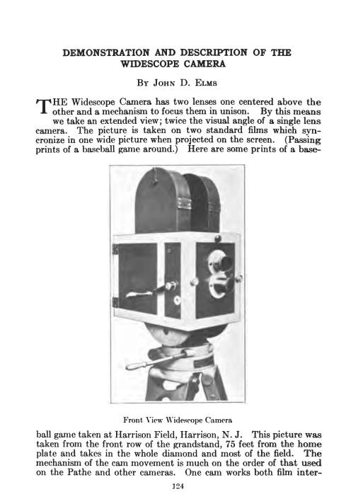
Certificate Vignette 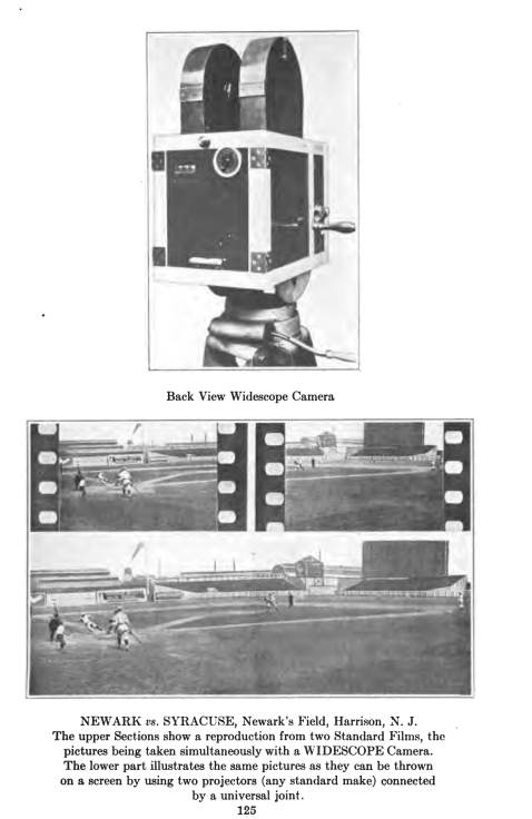
NEWARK us. SYRACUSE, Newark's Field, Harrison, N. J. The upper Sect.ions show a reproduction from two Standard Films, the pictures being taken simultaneously with a WIDESCOPE Camera. The lower part illustrates the same pictures as they can be thrown on a screen by using two projectors (any standard make) connected by a universal joint. DEMONSTRATION AND DESCRIPTION OF THE WIDESCOPE CAMERA THE Widescope Camera has two lenses one centered above the other and a mechanism to focus them in unison. By this means we take an extended view; twice the visual angle of a single lens camera. The picture is taken on two standard films which syncronize in one wide picture when projected on the screen. (Passing prints of a baseball game around.) Here are some prints of a baseball game taken at Harrison Field, Harrison, N. J. This picture was taken from the front row of the grandstand, 75 feet from the home plate and takes in the whole diamond and most of the field. The mechanism of the cam movement is much on the order of that used on the Pathe and other cameras. One cam works both film intermittances si~nultaneously. (Demonstrating.) The Widescope pictures are projected by connecting two projectors of any standard make with a rod and universal joints making one wide picture (exhibited photograph of two projectors connected.) We have not finished experiments of dissolving our pictures to a center, but this can be done by having two irises that will cut each side to a common center. I did not come with any prepared talk on this camera and hardly expected to be able to show it to you gentlemen in session. DISCUSSION OF MR. ELMS' DEMONSTRATION MR. HITCHINSI: had the opportunity of seeing the Widescope in operation and the results are really quite remarkable. Naturally, you would think there would be a see-sawing, but the results are very steady even with old projectors linked up hurriedly. The only practical difficulty is where the two pictures slightly overlap but that can be taken care of optically; otherwise, the scheme works nicely. MR. ELMS: We have demonstrated very successfully in a theater in Woodbridge, N. J., two theaters in Kansas City, Mo., and one theater in Los Angeles. We happened to be demonstrating in Los Angeles at the time Mr. Hays was there in July, therefore did not have as many of the technical men out as we hoped for. We also demonstrated in a theater in Binghamton, N. Y., where Dr. Hitchins saw it. Where some of our pictures had a great deal of white background, they showed a little light line where they overlapped. That is overcome in two ways. DR. MEES: I should like to know what the advantage is over using a lens of half the focal length with a mask. MR. ELMS: That would not give the same effect. This gives twice the angle of vision by using two lenses. DR. MEES: This could be obtained simply by halving the focal length. DR. KELLNERI: think Dr. Mees' scheme would produce difficulty in obtaining a wide field with a fast lens. DR. MEES: There is no need for a fast lens; the ordinary motion picture is taken at f / l l . DR. KELLNERI: was thinking of baseball pictures. DR. MEES: Yes, certainly. There is plenty of light on a baseball ground. DR. KELLNERI: had a discussion on the question of steadiness of the picture with Mr. Elms a few weeks ago, when I had the pleasure of seeing his camera. I wonder whether Dr. Hitchins mentioned this point for a purpose. MR. ELMS: NO, he did not know of our talk. DR. KELLNERI:t seems to me that there must be a parallax on close-ups. You take first the right and then the left picture but always the rights and the lefts from a different height. Although on a baseball field this does not matter, it seems to me that the fact that one picture is seen a little from above and the other one a little from below must cause a parallax which may be objectionable in close-ups. This parallax would make its presence known by an unsteadiness of the picture. If the object is far enough away the parallax becomes too small to cause trouble. MR. ELMS: If we are showing a close-up and a picture of about 30 or 40 feet away, without framing, it would not show perfect; the film passing through the apertures of the projectors for a close-up must be framed to match when changing to a distant view. A closeup at 4 or 5 feet necessarily includes no background; but if you could also take a background and close-up at the same time then it might be imperfect, but there would be no up and down motion. They would be out of line a little if not framed but no up and down motion. The step from close-up to distant view could be eliminated entirely when printing the positive. MR.R ICHARDSOUNn: fortunately I was unavoidably absent during Mr. Elms' talk. I understand, however, that we have now under consideration what is known as the "Widescope" camera. I have been invited to examine this device but did not make the trip necessary for the reason that even if you could really accomplish what you claim to, still there would be difficulty, or even impossibility in applying it in practice. In a theater or at least in the average theater, you have a condition which would seem to make the showing of such a picture impractical and highly objectionable. Often the front row of seats is as close as ten or fifteen feet from the screen and we comparatively seldom find the screen-to-front-row to exceed twentyfive feet. How is it possible to view such a picture as you propose at this distance, at least without a terrific eye strain? I have tried to drive into the heads of a s e c t s and exhibitors that there must be a minimum of sixteen feet between a sixteen foot picture and the front row of seats, with sufficient distance added for every addition to picture width to maintain the angle at that value. If you project a picture thirty to forty feet wide, as you propose, what are you going to do-rebuild the theater? MR. ELMS: A 20 foot screen is always at least 40 or 50 feet from the audience. We have demonstrated in three different cities besides Newark, N. J., and the general opinion is that our wide picture is restful to the eyes rather than tiring. Our invitation (extended some time ago) is still open to you, Mr. Richardson to come to Newark and see a demonstration. MR. RICHARDSOIN d:o not see how it can possibly be done, but will accept your invitation and come at as early a date as can be arranged. MR. Ems: We have been exceedingly anxious to have you see a demonstration of Widescope pictures knowing that you are one of the best known technical men of the industry. DR. MEES: I should be strongly in favor of this scheme if I thought it was any good because it uses twice as much film, and we make that film but, of course, you could use a wide angle lens and get the same effect. MR. ELMS: I beg to differ. You get distortion by use of a wide angle lens. We can use two of any lens and still get twice the angle of vision. DR. MEES: I leave it to my friend, Dr. Kellner, who knows a good deal about this, if you can't get equally good results by the use of a wide angle lens. DR. KELLNER: What's that? I did not listen, but I agree. (Laughter.) MR. ELMS: I should like to mention that Mr. Dennington saw a demonstration of our earlier pictures and he thought quite favorably of it at that time. I have nothing further to say except that we are making continual demonstrations and would be glad to meet any of you and take you out to our plant in Newark for a demonstration. MR. PORTER: Gentlemen: I think we are indebted to Mr. Elms for the demonstration of his camera. MR. JOHNSONI: should like to suggest that at the next meeting the gentleman gives a demonstration of the projection of the film. MR. PORTERI: think Mr. Elms will take this into consideration. MR. ELMS: I should be glad to do so.
Patent issued in 1923 Mar. 6, 1923. J. D. ELMS LENS FOCUSING DEVICE. Filed July 23, 1921 1,447,173 Patented Mar. 6, 1923. 1,447,173 UNITED STATES PATENT OFFICE. JOHN D. ELMS, OF WEST HEW BRIGHTON, NEW YORK, ASSIGNOR TO WIDESCOPE CAMERA CO., OF NEWARK, NEW JERSEY, A CORPORATION OF NEW JERSEY. loENS-FOCTTSINa DEVICE. Application filed July 23, 1921. Serial Wo. 486,951. To all whom it may concern: Be it known that I, John D. Elms, a citizen of the United States, residing at West New Brighton, in the county of Richmond, 5 borough of Richmond, city and State of New York, have invented new and useful Improvements in Lens-Focusing Devices, of which the following is'a full, clear, and exact specification. 10 My invention relates to lens focusing devices and refers particularly to devices capable of simultaneously focusing a plurality of divergent lenses. In the taking of widescope photographs. 16 in which it is desired to photograph abutting views upon a plurality of plates, or films, it is necessary that the plurality of lenses should be divergent with respect to each other and so positioned that their opti- 20 cal centers are in vertical alignment with each other. It is further requisite that the optical axis of each lens be at right angles to its photographic plate, or film, and hence these 25 plates, or films, will be at divergent angles with respect to each other. It is evident that, in, the production of widescope pictures, as above described, it is essential that all of the plurality of lenses 30 be in absolute focus upon their respective plates, or films, and that the independent focusing of each lens requires a considerable amount of time and causes the possibility of non-uniformity of focusing, thus rendering 86 the plurality of photographs non-uniform in clearness and precision. It is to be further noted that, as the optical axes of the different lenses are not in parallelism with respect to each other, the 40 movement of each lens, for purposes of focusing, must not be in the same plane as the remainder of the lenses. The device of my invention overcomes all of the difficulties of the individual and in- 46 dependent focusing of each of a plurality of divergent lenses and presents a means whereby all of a plurality of divergent lenses can be simultaneously and accurately focused rpon a purality of photographic plates, or 50 films. In the accompanying drawings, illustrating one form of the device of my invention, similar parts are designated by similar numerals. Figure 1 is a top plan view of one form 66 of my device. Figure 2 is a side view of Figure 1. Figure 3 is a back view of Figure 1. The particular form of the device of my invention, shown in the accompanying draw- 80 ings, comprises the camera bed-plate 10, to which are'fixedly attached the two U-shaped guide members 11, 11, the upper and lower sides of the guide members being spaced from each other for purposes described 86 hereafter. Slidable within the spaces between the sides of the guide members, 11,11, is a platform 12, to which is fixedly attached the right-angled plate 13, and to the latter, the right-angled plate 14 is fixedly attached. 7<> Fixedly attached to the upperly extended portion of the plate 13 is a lens-supporting plate 15 having apertures 16, 16 therein for the passage of light rays passing through lenses carried by the divergent lense holders 76 17. 17. The divergent lens holders 17, 17 are so positioned with respect to each other that the optical centers of their respective lenses are in vertical alignment with each other. 80 Fixedly attached to the camera base 10 are two right-angled plates 18, 18, to which are attached the two upright screens 19, 19, in each of which is an opening, or window 20, these windows being so positioned as to allow 85 the light rays passing through the lenses to impinge at rignt angles upon photographic plates, or films, behind the screens 19, 19. A right-angled plate 21 is fixedly attached to the camera bed-plate 10 and a threaded 00 bolt 22 passes through a hole in the plate 21, holes in the screens 19,19 and threads within a threaded hole in the plate 14 The bolt 22 has the two fixedly attached washers 23, 23 one on each side of the plate 21. 96 The lens holders 17, 17 are so positioned upon the supporting plate 15 that the optical axis of each lens is at right angles to its screen 19 and is centered with respect to its opening 20, and tbAis light passing through 100 the lenses, will impinge at right angles upon photographic plates, or films, behind, and parallel to, the screens 19, 19. If now the threaded bolt 22 be revolved. 1,447,178 the slidable platform 12 will be moved away from, or towards, the screens 19,19, and each . lens carried thereby will be moved equally with respect to its film as is the other lens & with respect to its film. It will thus be seen that the revolution of the bolt 22 will simultaneously focus both divergent sets of lenses upon their respective photographic plates, or films. 10 I do not limit myself to the particular size, shape, number or arrangement of parts, as shown and described, all of which may be varied without going beyond the scope of my invention, as shown, described and 16 claimed. What I claim is:-- 1. A lens focusing device, which comprises, a slidable platform, a plurality of divergent lenses carried by said platform, 20 a photographic film screen at right angles to the optical axis of each lens and having an opening to admit light rays passing through its lens and means whereby the plurality of lenses can be simultaneously 25 moved equally with respect to their respective screens. 2. A lens focusing device, which comprises, a slidable platform, a plurality of divergent lenses having their optical centers 30 in vertical alignment with each other carried by said platform, a photographic filni screen at right angles to the optical axis of each lens and having an opening to admit light rays passing through its lens and 35 means whereby the plurality of lenses can be simultaneously moved equally with respect to their respective screens. 3. A lens focusing device, which comprises, a camera bed-plate, a plurality of 40 guides carried by the bed-plate, a platform slidable within the guides, a plurality of divergent lenses carried by the platform, a photographic film screen at right angles to the optical axis of each lens carried by the 45 bed-plate and having an opening to admit light rays passing through its lea* sad means whereby the plurality of lenses can be simultaneously moved equally with respect to their respective screens. 4. A lens focusing device, which com- 60 prises, a camera bed-plate, a plurality of . guides carried by the bed-plate, a platform slidable within the guides, a plurality of divergent .lenses having their optical centers in vertical alignment with each other car- 55 ried by the platform, a photographic film screen at right angles to the optical axis of each lens carried by the bed^plate and having an opening to admit light rays passing through its lens and means whereby the plu- 60 rality of lenses can be simultaneously moved equally with respect to their respective screens. 5. A lens focusing device, which comprises, a slidable platform, a plurality of 65 divergent lenses having their optical centers in vertical alignment with each other carried by the platform, a photographic film screen at right angles to the optical axis of each lens and having an opening to admit 70 light rays passing through its lens and means whereby the optical centers of the lenses can be simultaneously moved equally with respect to their respective screens. 6. A tens focusing device, which com- 75 prises, a camera bed-plate, a plurality of guides carried by the bed-plate, a platform slidable within the guides, a plurality of divergent lenses having their optical centers in vertical alignment with each other car- 80 ried by the platform, a photographic film screen at right angles to the optical axis of. each lens carried by the bed-plate and having an opening to admit light rays passing through its lens and means whereby the 85 optical centers of the lenses can be.simultaneously moved equally with respect to their respective screens. Signed at New York city in the county of New York and State of New York this 90 '1st day of July, 1921. JOHN D. ELMS. History collected by OldCompany.com.
Certificate Vignette
NEWARK us. SYRACUSE, Newark's Field, Harrison, N. J. The upper Sect.ions show a reproduction from two Standard Films, the pictures being taken simultaneously with a WIDESCOPE Camera. The lower part illustrates the same pictures as they can be thrown on a screen by using two projectors (any standard make) connected by a universal joint.
Patent issued in 1923 Mar. 6, 1923. J. D. ELMS LENS FOCUSING DEVICE. Filed July 23, 1921 1,447,173 Patented Mar. 6, 1923. 1,447,173 UNITED STATES PATENT OFFICE. JOHN D. ELMS, OF WEST HEW BRIGHTON, NEW YORK, ASSIGNOR TO WIDESCOPE CAMERA CO., OF NEWARK, NEW JERSEY, A CORPORATION OF NEW JERSEY. loENS-FOCTTSINa DEVICE. Application filed July 23, 1921. Serial Wo. 486,951. To all whom it may concern: Be it known that I, John D. Elms, a citizen of the United States, residing at West New Brighton, in the county of Richmond, 5 borough of Richmond, city and State of New York, have invented new and useful Improvements in Lens-Focusing Devices, of which the following is'a full, clear, and exact specification. 10 My invention relates to lens focusing devices and refers particularly to devices capable of simultaneously focusing a plurality of divergent lenses. In the taking of widescope photographs. 16 in which it is desired to photograph abutting views upon a plurality of plates, or films, it is necessary that the plurality of lenses should be divergent with respect to each other and so positioned that their opti- 20 cal centers are in vertical alignment with each other. It is further requisite that the optical axis of each lens be at right angles to its photographic plate, or film, and hence these 25 plates, or films, will be at divergent angles with respect to each other. It is evident that, in, the production of widescope pictures, as above described, it is essential that all of the plurality of lenses 30 be in absolute focus upon their respective plates, or films, and that the independent focusing of each lens requires a considerable amount of time and causes the possibility of non-uniformity of focusing, thus rendering 86 the plurality of photographs non-uniform in clearness and precision. It is to be further noted that, as the optical axes of the different lenses are not in parallelism with respect to each other, the 40 movement of each lens, for purposes of focusing, must not be in the same plane as the remainder of the lenses. The device of my invention overcomes all of the difficulties of the individual and in- 46 dependent focusing of each of a plurality of divergent lenses and presents a means whereby all of a plurality of divergent lenses can be simultaneously and accurately focused rpon a purality of photographic plates, or 50 films. In the accompanying drawings, illustrating one form of the device of my invention, similar parts are designated by similar numerals. Figure 1 is a top plan view of one form 66 of my device. Figure 2 is a side view of Figure 1. Figure 3 is a back view of Figure 1. The particular form of the device of my invention, shown in the accompanying draw- 80 ings, comprises the camera bed-plate 10, to which are'fixedly attached the two U-shaped guide members 11, 11, the upper and lower sides of the guide members being spaced from each other for purposes described 86 hereafter. Slidable within the spaces between the sides of the guide members, 11,11, is a platform 12, to which is fixedly attached the right-angled plate 13, and to the latter, the right-angled plate 14 is fixedly attached. 7<> Fixedly attached to the upperly extended portion of the plate 13 is a lens-supporting plate 15 having apertures 16, 16 therein for the passage of light rays passing through lenses carried by the divergent lense holders 76 17. 17. The divergent lens holders 17, 17 are so positioned with respect to each other that the optical centers of their respective lenses are in vertical alignment with each other. 80 Fixedly attached to the camera base 10 are two right-angled plates 18, 18, to which are attached the two upright screens 19, 19, in each of which is an opening, or window 20, these windows being so positioned as to allow 85 the light rays passing through the lenses to impinge at rignt angles upon photographic plates, or films, behind the screens 19, 19. A right-angled plate 21 is fixedly attached to the camera bed-plate 10 and a threaded 00 bolt 22 passes through a hole in the plate 21, holes in the screens 19,19 and threads within a threaded hole in the plate 14 The bolt 22 has the two fixedly attached washers 23, 23 one on each side of the plate 21. 96 The lens holders 17, 17 are so positioned upon the supporting plate 15 that the optical axis of each lens is at right angles to its screen 19 and is centered with respect to its opening 20, and tbAis light passing through 100 the lenses, will impinge at right angles upon photographic plates, or films, behind, and parallel to, the screens 19, 19. If now the threaded bolt 22 be revolved. 1,447,178 the slidable platform 12 will be moved away from, or towards, the screens 19,19, and each . lens carried thereby will be moved equally with respect to its film as is the other lens & with respect to its film. It will thus be seen that the revolution of the bolt 22 will simultaneously focus both divergent sets of lenses upon their respective photographic plates, or films. 10 I do not limit myself to the particular size, shape, number or arrangement of parts, as shown and described, all of which may be varied without going beyond the scope of my invention, as shown, described and 16 claimed. What I claim is:-- 1. A lens focusing device, which comprises, a slidable platform, a plurality of divergent lenses carried by said platform, 20 a photographic film screen at right angles to the optical axis of each lens and having an opening to admit light rays passing through its lens and means whereby the plurality of lenses can be simultaneously 25 moved equally with respect to their respective screens. 2. A lens focusing device, which comprises, a slidable platform, a plurality of divergent lenses having their optical centers 30 in vertical alignment with each other carried by said platform, a photographic filni screen at right angles to the optical axis of each lens and having an opening to admit light rays passing through its lens and 35 means whereby the plurality of lenses can be simultaneously moved equally with respect to their respective screens. 3. A lens focusing device, which comprises, a camera bed-plate, a plurality of 40 guides carried by the bed-plate, a platform slidable within the guides, a plurality of divergent lenses carried by the platform, a photographic film screen at right angles to the optical axis of each lens carried by the 45 bed-plate and having an opening to admit light rays passing through its lea* sad means whereby the plurality of lenses can be simultaneously moved equally with respect to their respective screens. 4. A lens focusing device, which com- 60 prises, a camera bed-plate, a plurality of . guides carried by the bed-plate, a platform slidable within the guides, a plurality of divergent .lenses having their optical centers in vertical alignment with each other car- 55 ried by the platform, a photographic film screen at right angles to the optical axis of each lens carried by the bed^plate and having an opening to admit light rays passing through its lens and means whereby the plu- 60 rality of lenses can be simultaneously moved equally with respect to their respective screens. 5. A lens focusing device, which comprises, a slidable platform, a plurality of 65 divergent lenses having their optical centers in vertical alignment with each other carried by the platform, a photographic film screen at right angles to the optical axis of each lens and having an opening to admit 70 light rays passing through its lens and means whereby the optical centers of the lenses can be simultaneously moved equally with respect to their respective screens. 6. A tens focusing device, which com- 75 prises, a camera bed-plate, a plurality of guides carried by the bed-plate, a platform slidable within the guides, a plurality of divergent lenses having their optical centers in vertical alignment with each other car- 80 ried by the platform, a photographic film screen at right angles to the optical axis of. each lens carried by the bed-plate and having an opening to admit light rays passing through its lens and means whereby the 85 optical centers of the lenses can be.simultaneously moved equally with respect to their respective screens. Signed at New York city in the county of New York and State of New York this 90 '1st day of July, 1921. JOHN D. ELMS. History collected by OldCompany.com.
")
")
")
 - Delaware 1923")
